Product Brief Introduction
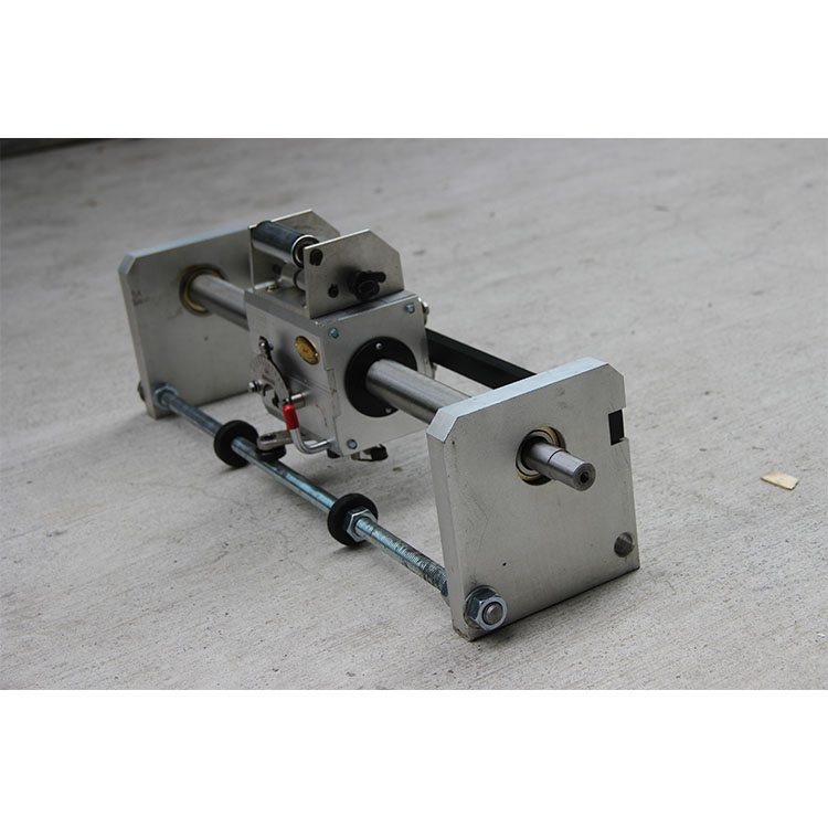
we can provide a wide range of smooth shaft(rolling rings) traverse drives with different types,which can meet various requirements of our customers.
The rolling ring Linear drives provided by us are characterized wuth a lot of features such as the stepless speed adjustment,the instantaneous reversal, the Drive position adjustment just by means of the release lever,the special treatment of the Smooth Shaft,the Traverse Drive being mounted with selected high performance bearings,and long service life.

Installation and Debugging
Release Lever. There are two positions,i.e, the working position “1” and the releasing position “0”. When the lever sits at the working position,the bearing above it are at the lifting position and apply pressure to the Smooth Shaft and so make the Traverse Drive generate the thrust force.when the lever sits at the Releasing Position,the earings above it are at the falling position and by pushing with hands you can make the Rolling ring drive unit slide freely on the Smooth Shaft.Before install the Smooth Shaft,pull the Release Lever and check if the bearings can be moved up and down.
Mounting the Smooth Shaft By putting the Release Lever at the released position”0″ and adjusting the sheathes at the both sides of drive you can install the shaft into the Traverse Drive,and then pull the Release Lever to the working position”1″
Adjusting the Guide Roller The Guide Rollers can be used to ensure the working stability of the traverse drive unit.The Guide Frame is eccentric.when the space between the Guide Roller and the Guide Bar is not correct,adjustment can be made by loosing the screws and turning the Guide Frame.
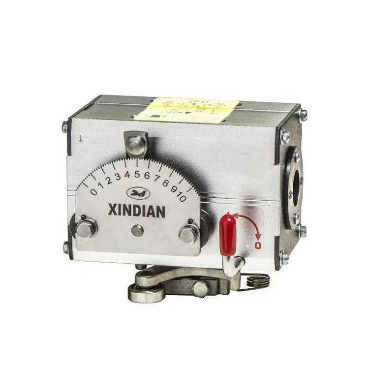
Determining Direction of Rotation The downward turning of the shaft when facing the scale dial is defined as the positive rotation,in which case the trigger roller of the reverseal arm shall point to the side where the scale dial is.While the upward turning of the shaft when you looking in front of scale dial is reverse rotation and in such case the trigger roller of the reversal arm shall point to the backward side of the traverse housing so that the reversal of Roll Ring Traverse Unit can be realized. The roduct is normally assembled with the shaft turning positively when leaving the factory.
Rotation Speed of Shaft The take-up bobbin speed shall be higher than the shaft speed of wire traverse unit.The speed ratio available ranges from5:1 to 1:1.If the wire size is small the ratio will be large and if the wire size is large the ratio will be small.
Pitch Adjustment The scale values 1-10 on the dial are the adjustment range of pitches,and not the numeric value of pitch.The pitch is matched to the thickness of the wire/cable.when the Indicator is at the left of the Scale Dial,the Traverse Drive dwells on the Shaft without any movement.in addtion,the adjustment should not be made to the maximum pitch position.when adjustment is made the Indicator shall be disengaged completely from the Serrated Scale Dial.
Mounting the wire Guide Pulley/Roller When mounting the wire part special care should be taken not to turn the screw too deeply into the box,in order to avoid influence the normal working conditions of the internal mechanism.
similar to uhing traverse unit Adjust the positions of two reversal end stops on the lead screw to make the travel match the position and length of the take-up bobbin.